Sentinel with Logic Apps – Automate IP Address Analysis and Threat Response

In today’s interconnected digital landscape, maintaining robust security measures is paramount for businesses of all sizes. Threat actor’s constantly evolve their tactics, necessitating proactive approaches to identify and mitigate potential risks. Microsoft Sentinel, coupled with Logic Apps offers a powerful solution to enhance security operations, enabled organizations to swiftly detect and respond to threats.

In this blog post, we’ll explore how to leverage Logic Apps to extract IP addresses from security events in Microsoft Sentinel and subsequently retrieve abuse scores from IPDB services. This process empowers security teams to gain deeper insights into potential threats and take decisive action to safeguard their systems.

Step 1: KQL Query

Let’s take an example where we have an analytics rule with a KQL query defined to raise an incident whenever any delete or purge activity occurs within Azure Key Vault.

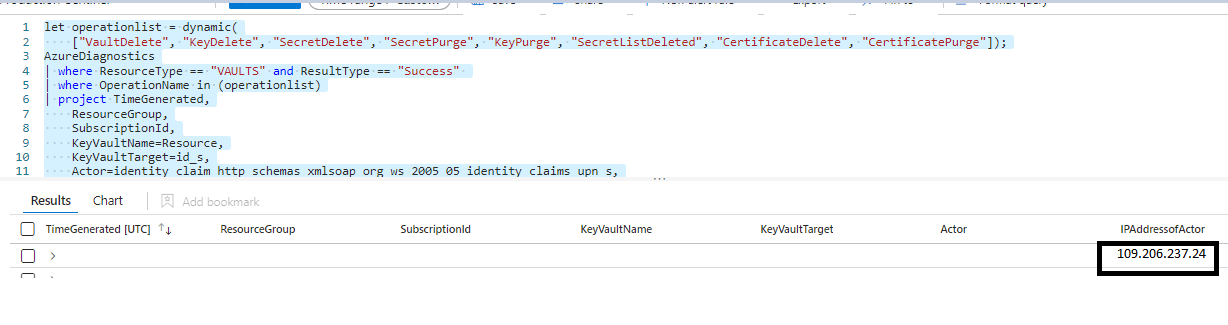
let operationlist = dynamic(
["VaultDelete", "KeyDelete", "SecretDelete", "SecretPurge", "KeyPurge", "SecretListDeleted", "CertificateDelete", "CertificatePurge"]);
AzureDiagnostics
| where ResourceType == "VAULTS" and ResultType == "Success"
| where OperationName in (operationlist)
| project TimeGenerated,
ResourceGroup,
SubscriptionId,
KeyVaultName=Resource,
KeyVaultTarget=id_s,
Actor=identity_claim_http_schemas_xmlsoap_org_ws_2005_05_identity_claims_upn_s,
IPAddressofActor=CallerIPAddress,
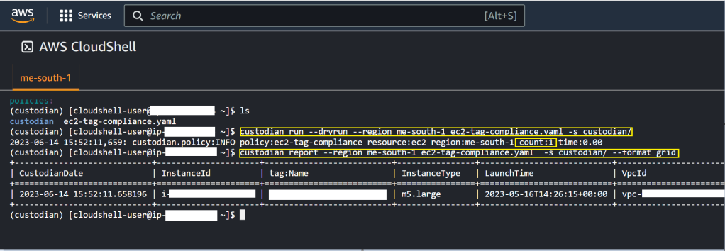
OperationName

When i run this query, here is how the output looks like.

For the sake of data privacy, i have masked most of the information and purposely shown an abused IP address.

Now that we know our KQL query is able to detect deletion and purges along with IP Address of actor, lets put this all in an analytics rule.

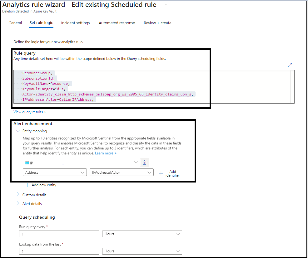
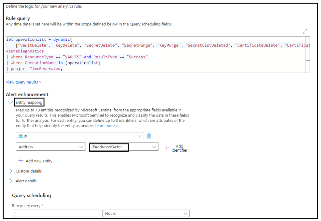
Step 2: Setting up Analytics rule

Here we set up a scheduled query through analytics to run once every hour and detect if any deletion activity is carried out across all key vaults in Azure. This query is also responsible for triggering the logic app that will calculate the abuse score of the IP address via which deletion was carried out.

The KQL query that we created above exposes a column IPAddressofActor. We need to map this column to an entity as shown below.

Step 3: Logic Apps

Let us configure a logic app that automatically gets triggered when our scheduled query rule performs a detection.

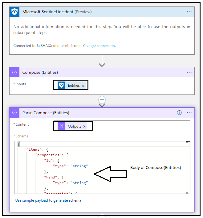
The first action is the Trigger. Basically, this tells the logic app to trigger whenever a Microsoft Sentinel Incident is created. You can learn more about it here

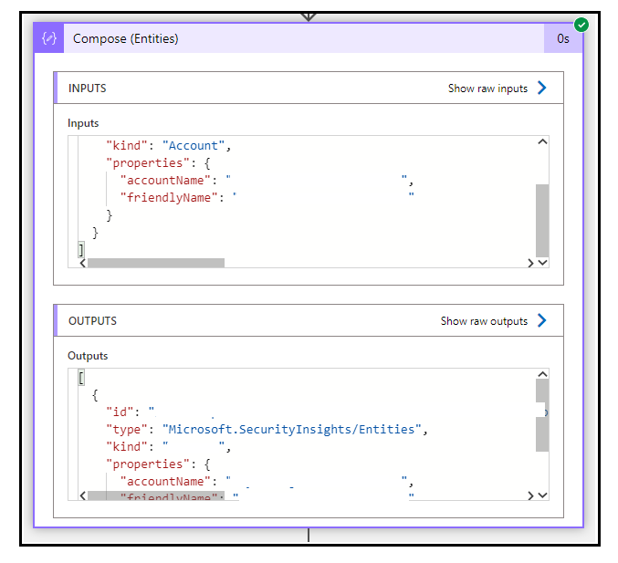
In the next action Compose(Entities), we use the compose action to grab the entities. You can see all the entities mapped to the incident become available as output of this action.

The action, Parse Compose(Entities) is used to parse the JSON output made available from Compose(Entities) and make the value available as a variable.

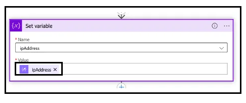
In the action, Set Variable, we set the variable ipAddress made available from the Parse Compose(Entities) action.

Action 1,2,3 (Trigger -> Compose Entities -> Parse Compose Entities)

Output of Compose (Entities) as seen in Run History

Action 4 (Set variable)

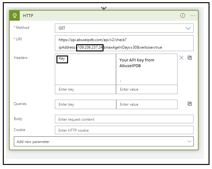
This is the final action, we configure an HTTP trigger and call the AbuseIPDB API to get abuse report and abuse score.

URI - 
https://api.abuseipdb.com/api/v2/check?ipAddress=<ip_Address>&maxAgeInDays=30&verbose=true

Method - 
Get

Headers -
Key

In the below action, i have purposely hardcoded the ipAddress to show you the IP in question, you can pass the output of Set Variable action


Action 5 (HTTP)

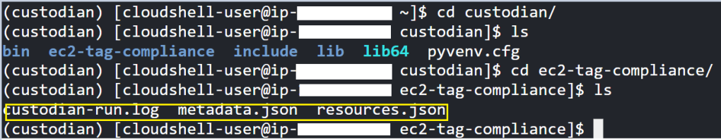
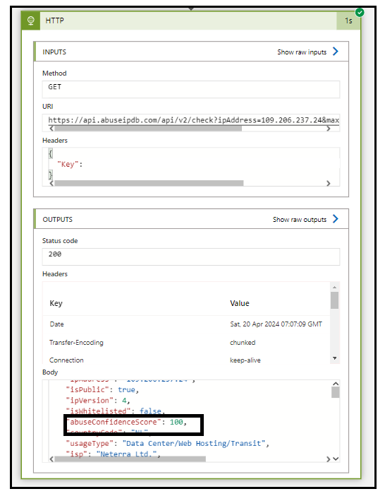
Here is how the output of the HTTP action looks like in the logic apps run history.

In the Body, you can see there is a parameter called “abuseConfidenceScore“. The abuse confidence score is the calculation evaluation of how abuse the IP is based on the users that reported it.


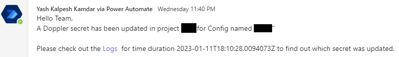
That’s it, now you can modify the logic app as per your own will to take a decision in the next step. You can use a Send Email action to send an email to your stake holder (Cybersecurity team) and let them know about this abusive IP that was involved in deletion and then they can block this IP address.

Step 4: Connecting it all together

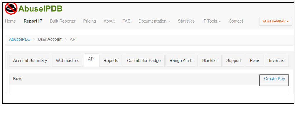
Note that you need to create an account in AbuseIPDB to get an API key which then needs to be used in HTTP action.

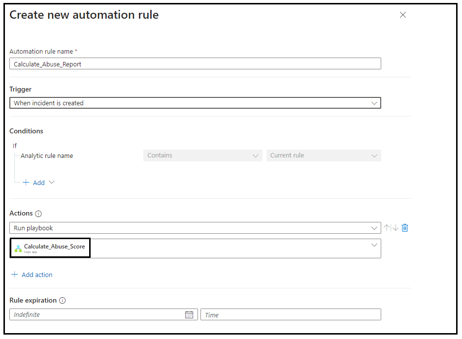
Once the Logic App is configured, you need to go back to your analytics detection rule in Sentinel and perform once last step to integrate your logic app with the rule as below.

Conclusion

By leveraging Logic Apps in conjunction with Microsoft Sentinel and IPDB, organizations can establish a robust security posture capable of swiftly identifying and mitigating potential threats. The seamless integration of these services enable automated threat detection, analysis and response, empowering security teams to stay ahead of evolving cyber threats.

In today’s ever changing threat landscape, proactive security measures are indispensable. With Logic Apps, organizations can harness the power of automation and intelligence to fortify their defenses and safeguard their assets against emerging threats.

Start harnessing the power of Logic Apps today and take proactive steps towards bolstering your security posture in an increasingly interconnected world.

Streamlining Governance Notifications in AWS Organizations with Automation

In the ever-evolving world of AWS, maintaining the security and organization of your accounts is paramount. If you’re managing multiple AWS accounts within an AWS Organization, you might be concerned about tracking changes such as the movement of an account from one Organizational Unit (OU) to another.

Fortunately, AWS offers robust tools to help you keep tabs on these changes. In this blog post, we’ll explore how you can use a serverless Lambda function in conjunction with AWS CloudTrail and CloudWatch to be promptly notified whenever an account is moved from one OU to another.

Understanding the AWS Organization

AWS Organizations simplifies the management of multiple AWS accounts. It enables you to organize accounts into OUs, allowing you to better control access policies, billing, and resource sharing. However, with great power comes the need for oversight.

The Tools at Your Disposal

  1. AWS CloudTrail: CloudTrail records all API calls in your AWS account. By enabling it at the Organization level, you can track every change within the Organization, including account relocations.
  2. AWS CloudWatch Events: CloudWatch Events allow you to respond to changes in your AWS environment. By creating rules that trigger on specific CloudTrail events, you can respond in real-time.
  3. AWS Lambda: Lambda is a serverless compute service that allows you to run code without provisioning or managing servers. It’s the glue that ties everything together in our solution.

The Lambda Function

The first step in this process is to create a Lambda function that will be triggered by a CloudWatch Event. This function should be equipped to parse the event, extract relevant information, and send out notifications when an account is moved between OUs.

Here’s a high-level overview of the Lambda function’s steps:

  1. Receive the CloudTrail event.
  2. Parse the event to identify changes in OU memberships.
  3. If the event indicates an account relocation, send out a notification using your preferred method (e.g., email, SNS, Slack).
import json
import boto3

def get_ou_name(ou_id):
    org_client = boto3.client('organizations')
    response = org_client.describe_organizational_unit(OrganizationalUnitId=ou_id)
    return response['OrganizationalUnit']['Name']

# extract_user_domain function
def extract_user_domain(principal_id):
    parts = principal_id.split(':')
    if len(parts) == 2:
        return parts[1]
    return "Unknown"

def lambda_handler(event, context):
    
    sns_topic_arn = "arn:aws:sns:us-east-1:xxxx1234xxxx:notify_on_move_account_sns"

    #if event detail has MoveAccount, then grab source and destination ou and send email via sns
    if event['detail']['eventName'] == 'MoveAccount':
        # Parse the CloudTrail event details
        source_ou_id = event['detail']['requestParameters']['sourceParentId']
        destination_ou_id = event['detail']['requestParameters']['destinationParentId']
        account_id = event['detail']['requestParameters']['accountId']
        principal_id=event['detail']['userIdentity']['principalId']
        user_domain = extract_user_domain(principal_id)
        
        source_ou_name = get_ou_name(source_ou_id)
        destination_ou_name = get_ou_name(destination_ou_id)

        # Prepare the email notification message
        
        message = f"CloudTrail event occurred: MoveAccount\n"
        message += f"Account ID: {account_id}\n"
        message += f"Source OU: {source_ou_name} (ID: {source_ou_id})\n"
        message += f"Destination OU: {destination_ou_name} (ID: {destination_ou_id})\n"
        message += f"Account Moved By: {user_domain}" 
        # Send email notification
        sns_client = boto3.client("sns")
        sns_client.publish(TopicArn=sns_topic_arn, Message=message)

    return {
        "statusCode": 200,
        "body": json.dumps("Email sent successfully")
    }

Here, you define a function get_ou_name(ou_id) that retrieves the name of an Organizational Unit (OU) based on its ID using the AWS Organizations client. This function will help you translate OU IDs into human-readable OU names.

This function extract_user_domain(principal_id) is used to extract the user or domain from the “principalId” field in the CloudTrail event. It splits the “principalId” on the colon character and, if two parts exist, it returns the second part, which typically represents the user or domain. If there are not two parts, it returns “Unknown.”

In the lambda_handler function, you specify the ARN (Amazon Resource Name) of the AWS Simple Notification Service (SNS) topic that will be used for sending notifications. Make sure to replace "arn:aws:sns:us-east-1:xxxx1234xxxx:notify_on_move_account_sns" with the actual ARN of your SNS topic.

The IF condition, checks if the CloudTrail event’s “eventName” is equal to ‘MoveAccount’, which indicates that an AWS account is being moved within your AWS Organization. If true then the logic extract details from the CloudTrail event. It collects the source OU ID, destination OU ID, the AWS account ID that’s being moved, and the “principalId” field to identify the user responsible for the move. It also uses the get_ou_name function to convert OU IDs into OU names.


Setting Up CloudWatch Rules

With the Lambda function ready, you can create a CloudWatch Event rule. This rule specifies the conditions under which the Lambda function should be triggered. In this case, you’ll want to create a rule that captures events related to account movements within your AWS Organization.


Setting Up SNS

Configure an Amazon SNS (Simple Notification Service) topic and a subscription to roll out email notifications whenever an AWS account move is triggered by a Lambda function, follow these steps:

  1. Create an SNS Topic:
    • Log in to the AWS Management Console.
    • Navigate to the Amazon SNS service.
    1. Click on “Topics” in the SNS dashboard.
    2. Click the “Create topic” button.
    • Provide a name and a display name for your SNS topic.
    • Optionally, add any tags to help organize your topics.
    • Click “Create topic.”
  2. Create an Email Subscription:
    • After creating the SNS topic, select the topic you just created.
    1. Click the “Create subscription” button.
    2. Choose “Email” as the protocol.
    3. Enter the email addresses of the recipients you want to notify about account moves. You can add multiple email addresses, separating them with commas.
    4. Click “Create subscription.”
    • You will receive a confirmation email at the specified email addresses. Follow the link in the email to confirm the subscription.

TESTING

Test your Lambda function to ensure that it publishes messages to the SNS topic when an account move is triggered. You should receive email notifications at the specified email addresses.


Overall, automating AWS account move notifications is a value-add because it enhances operational efficiency, improves security, and ensures compliance, ultimately contributing to a well-managed and accountable AWS environment. It streamlines the communication process and allows organizations to respond more effectively to changes within their cloud infrastructure.

Implementing Automatic EC2 Instance Shutdown with Cloud Custodian and Jenkins

This blog post is Part 2 of our series on Cloud Custodian for implementing Governance as Code in Cloud.

The previous blog post covered a basic understanding of Cloud Custodian, sort of getting familiar conceptually. It did not cover an actual business case but in this blog post we’ll walk through how to set up automatic EC2 instance shutdowns using Cloud Custodian, and integrate it seamlessly into your Jenkins CI/CD pipeline.

Managing costs in your AWS (Amazon Web Services) environment is crucial, and one effective way to achieve cost savings is by automatically shutting down EC2 instances during non-business hours or when they are not in use.

To achieve this, our Jenkins CI/CD pipeline is configured to trigger the Makefile, which compiles and prepares the necessary code for executing our Cloud Custodian policies. These policies, driven by Jinja templates, are then deployed to AWS environment, where they autonomously manage EC2 instances, ensuring cost-efficiency and resource optimization.

Here is what our directory structure looks like –

cloud-custodian/
│
├── policies/
│   │
│   # Cloud custodian policy file dynamically getting created here
│   │
├── templates/
│   │
│   └── cloud-custodian/
│       │
│       # Jinja templates for Cloud Custodian policies
│       │
│       └── instance-auto-shutdown.yaml.j2
│
└── tools/
    │
    │
    └── mugc.py
│
JenkinsFile
Makefile

Targeting Makefile from JenkinsFile :

Our Jenkinsfile will basically trigger a target in Makefile within which we will build our policy file using a Jinja template.

To target a Makefile from within a Jenkinsfile, you can use a sh (shell) step in your Jenkins Pipeline. You’ll execute the make command with the desired Makefile target as an argument.

pipeline {
    agent any

    stages {
        stage('Connect to AWS') {
            steps {
                script {
                 // Generate AWS CLI profile for assuming IAM role
                }
            }
        }
        stage('Build and Target Make') {
            steps {
                // Navigate to the directory containing your Makefile
                dir('path/to/your/makefile/directory') {
                    // Execute the Makefile target
                    sh "set +x;make ${make_action} TERRAFORM_FOLDER=${terraform_folder_path} \
                      AWS_ACCOUNT_ID=${pass var for your AWS account} \
                      AWS_REGION=${region} \
                      LAYER=cloud-custodian "
                }
            }
        }
    }
    
    // Add post-build actions or notifications as necessary
}

Makefile :

There are some good to know points which i think are important before you get your hands dirty with the Makefile that i am using.

  • Phony targets are targets that do not represent actual files, but rather they are used to specify a sequence of tasks or dependencies that need to be executed when the target is invoked.
  • Yasha is a Python library and command-line tool that provides functionality for working with Jinja2 templates. Specifically, it’s designed to render or generate text files based on Jinja2 templates and input data.
  • ?= is useful in Makefiles when you want to provide default values for variables but also allow users to override those defaults by setting the variables externally or within the Makefile itself.
# Declare the "all" target as a phony target. 
# Phony targets are not associated with files and always execute their commands.
.PHONY: all
# The default target, "all," depends on the "install-dependencies" target.
all: install-dependencies

# Variable assignments with conditional defaults.
TERRAFORM_FOLDER ?= ""
LAYER ?= ""
LAYER_FOLDER ?= "cloud-custodian"
AWS_REGION ?= "eu-west-1"
AWS_ACCOUNT_ID ?= ""
AWS_ACCOUNT_AUTO_SHUTDOWN ?= "<Target AWS Account ID for this policy>"

# Target to install dependencies.
install-dependencies:
    pip3 install yasha
    aws --version

# Target to render Cloud Custodian policies.
cloud-custodian-render-policies: install-dependencies
    @echo -e "\nRendering Cloud Custodian Policies\n" && \
    cd ${LAYER_FOLDER} && \
    yasha --aws_shared_services_account_id=${AWS_ACCOUNT_ID} --aws_account_auto_shutdown_id=${AWS_ACCOUNT_AUTO_SHUTDOWN} -o policies/instance-auto-shutdown.yaml templates/cloud-custodian/instance-auto-shutdown.yaml.j2 && \
    cat policies/instance-auto-shutdown.yaml

# Target to perform a dry run of Cloud Custodian policies.
cloud-custodian-plan: cloud-custodian-render-policies
    cd ${LAYER_FOLDER} && \
    custodian run --dryrun --region eu-west-1 --region me-south-1 --profile ${AWS_ACCOUNT_ID}-profile policies/instance-auto-shutdown.yaml -s tools/output

# Target to apply Cloud Custodian policies.
cloud-custodian-apply: cloud-custodian-plan
    cd ${LAYER_FOLDER} && \
    custodian run --region eu-west-1 --region me-south-1 --profile ${AWS_ACCOUNT_ID}-profile policies/instance-auto-shutdown.yaml -s tools/output
  1. The all target is declared as phony because it doesn’t correspond to an actual file, and it depends on the install-dependencies target.
  2. Variable assignments with conditional defaults are used to define variables that can be overridden by users when running the Makefile. If a variable is not already defined or is empty, it is assigned the specified default value.
  3. The install-dependencies target installs the necessary dependencies, yasha and the AWS CLI tool.
  4. The cloud-custodian-render-policies target depends on install-dependencies. It renders Cloud Custodian policies using the yasha tool and specifies the required parameters. It also displays the rendered policy for inspection.
  5. The cloud-custodian-plan target depends on cloud-custodian-render-policies. It performs a dry run of the Cloud Custodian policies using the custodian run command, specifying the AWS region and profile.
  6. The cloud-custodian-apply target depends on cloud-custodian-plan. It applies the Cloud Custodian policies to the specified AWS regions and profile.

Jinja Template :

policies:
  - name: auto-shutdown-ec2-{{ aws_account_auto_shutdown_id }}
    mode:
      type: periodic
      function-prefix: lz-cloud-custodian-
      schedule: "rate(5 minutes)"
      role: arn:aws:iam::{{ aws_shared_services_account_id }}:role/CloudCustodianRole
      execution-options:
        assume_role: arn:aws:iam::{{ aws_account_auto_shutdown_id }}:role/CloudCustodianAssumeRole
        metrics: aws
    resource: ec2
    filters:
      - type: offhour
        tag: CUSTODIANOFF
        default_tz: Asia/Dubai
        offhour: 15
    actions:
      - stop
      - type: tag
        tags:
          StoppedByCloudCustodian: Instance stopped by auto-shutdown-ec2-{{ aws_account_auto_shutdown_id }}.
  1. The Jinja2 template is used to generate Cloud Custodian policy definitions for EC2 instances.
  2. {{ aws_account_auto_shutdown_id }} and {{ aws_shared_services_account_id }} are Jinja2 placeholders, which will be replaced with actual values when rendering the template. We are passing both these values via Makefile.
  3. The policy has the following components:
    • name: Specifies the name of the policy, including the AWS account ID for auto-shutdown.
    • mode: Defines the execution mode of the policy. It’s set to periodic, running every 5 minutes. It also specifies the IAM role to assume (role) and additional execution options.
    • resource: Specifies the AWS resource type that this policy targets, which is EC2 instances in this case.
    • filters: Contains filter rules to select the instances to which the policy will be applied. In this case, it uses a filter of type offhour to target instances tagged with CUSTODIANOFF. It sets the default time zone to “Asia/Dubai” and the off-hour time to 15 (3:00 PM).
    • actions: Lists the actions to take on the selected instances. In this policy, it specifies actions to stop the instances based on filter and tag them with a message indicating that they were stopped by Cloud Custodian.
    • In short this Cloud Custodian policy will be deployed as a Lambda function in the target AWS account which will run every 5 minutes, filter the ec2 instances that are running and have a tag as CUSTODIANOFF and then if the current time is ahead of off-hour time i.e 03:00 PM then turn off that ec2 instance and also configure a tag on that ec2 instance with a message indicating that it was shutdown by Cloud Custodian.

Execution and verifying the results :

Jenkins console output –

If you remember in our Makefile we had a CAT cmd to display the content of the policy file that is being generated by Jinja template.
Here is an output of the CAT cmd showing up in the console output of my Jenkins run –

Lambda function in AWS –

Lets navigate to our AWS account and check if the Lambda function is deployed and if deployed check the logs to see if the cloud custodian has detected any ec2 instance that has tag set as CUSTODIANOFF which it needs to turn off.

As you can see the logs of the Lambda function clearly show that the Cloud Custodian policy was able to filter 1 ec2 instance that had CLOUDCUSTODIANOFF tag and which was in running state.

Cloud Custodian then as per the ACTIONS configured on filter went ahead and stopped the ec2 instance while also tagging that ec2 instance with a message that the instance was stopped by Cloud Custodian.

In this blog post, we’ve explored a powerful and efficient solution for managing your AWS EC2 instances: Cloud Custodian combined with Jenkins automation. By leveraging the capabilities of Cloud Custodian and Jenkins, you can ensure that your EC2 instances are stopped at specific times or under specific conditions, helping you optimize costs, enhance security, and streamline resource management.

Here are the key takeaways :

  1. Cost Optimization: Automatically stopping EC2 instances during off-hours or when they are not in use can significantly reduce your AWS costs. Cloud Custodian makes it easy to define and enforce such policies.
  2. Enhanced Security: Stopping instances that are not actively needed can improve your AWS environment’s security posture by reducing the attack surface.
  3. Jenkins Integration: Jenkins acts as the orchestrator, allowing you to schedule Cloud Custodian policy executions at specific times or in response to events.
  4. Flexibility: Cloud Custodian policies are highly customizable, enabling you to tailor them to your organization’s specific needs and compliance requirements.
  5. Resource Optimization: By stopping instances when they are not required, you free up resources for other workloads, making better use of your AWS infrastructure.
  6. Continuous Improvement: Use Jenkins pipelines to continuously update and refine your Cloud Custodian policies as your infrastructure evolves.

Implementing this solution can lead to cost savings, improved security, and better resource management in your AWS environment. Whether you’re managing a small development environment or a large-scale production system, Cloud Custodian and Jenkins offer a flexible and scalable approach to EC2 instance management.

Don’t hesitate to start implementing these practices in your AWS environment. If you have questions or need further assistance, please feel free to reach out. Thank you for reading, and happy cloud management with Cloud Custodian and Jenkins!

RBAC in AKS – This vs That

Over a cup of coffee at City Centre, Deira , I was brainstorming with one of my colleagues on the most viable option to go ahead with for configuring access on AKS cluster. We had a really interesting discussion and that’s when I thought that this topic deserves a blog post.

There are 3 options that are available for configuring authentication and authorization in AKS –

  1. Local accounts with Kubernetes RBAC
  2. Azure AD authentication with Kubernetes RBAC
  3. Azure AD authentication with Azure RBAC

For those of you who are new to AKS, the official in-depth documentation for access configuration that explains all these three methods will get easier to digest if you go through this blog post.


Local accounts with Kubernetes RBAC

If Azure Active Directory integration is not enabled then by default AKS uses local accounts for authentication.

You have to then rely on client certificates (based on x509 certificates), bearer tokens, OpenID Connect tokens, Service account tokens, Bootstrap tokens etc. This is covered in detail here

User management becomes a bit difficult while using this option because it becomes difficult to differentiate between the user access.

Choose this option only if Azure AD integration is not possible or if you do not want your cluster users to be a part of Azure AD.


Azure AD authentication with Kubernetes RBAC

You will need Azure Active Directory integration enabled to access this option.

With this option, the authentication to AKS is delegated by Azure AD whereas authorization needs to be defined within the yaml manifests i.e. RoleBinding

With this option, user management becomes a bit organized because it allows you to define what role you are configuring for a user or a group of users with respect to authorization.

Lets try to understand this with the help of a scenario.

Suppose you are designing an AKS cluster based on user roles where you want –

  • Solution architect to be a cluster-admin
    • Allows super-user access to perform any action on all resources in every namespace
  • Developers to have an edit access
    • Read/write access to most resources in that namespace but no permission to create rolebindings
  • Operations engineers to have a view access
    • Read only access to most resources in that namespace but no permission to create rolebindings and access secrets

Here is what your RoleBinding YAML file would look like for your solution architect’s (cluster-admins) –

apiVersion: rbac.authorization.k8s.io/v1
kind: RoleBinding
metadata:
  name: cluster-admin-role-binding
  namespace: TechCOE
subjects:
  - kind: Group (This can be a group of a user)
    name: <Azure AD group ID (guid)>
    apiGroup: rbac.authorization.k8s.io
roleRef:
  kind: ClusterRole
  name: cluster-admin 
  apiGroup: rbac.authorization.k8s.io

Here is what your RoleBinding YAML file would look like for your developers (edit)-

apiVersion: rbac.authorization.k8s.io/v1
kind: RoleBinding
metadata:
  name: edit-role-binding
  namespace: TechCOE
subjects:
  - kind: Group (This can be a group of a user)
    name: <Azure AD group ID (guid)>
    apiGroup: rbac.authorization.k8s.io
roleRef:
  kind: ClusterRole
  name: edit
  apiGroup: rbac.authorization.k8s.io

Here is what your RoleBinding YAML file would look like for your operations team (view)-

apiVersion: rbac.authorization.k8s.io/v1
kind: RoleBinding
metadata:
  name: view-role-binding
  namespace: TechCOE
subjects:
  - kind: Group
    name: <Azure AD group ID (guid)>
    apiGroup: rbac.authorization.k8s.io
roleRef:
  kind: ClusterRole
  name: view
  apiGroup: rbac.authorization.k8s.io

From the above 3 examples it becomes clear as to how Azure AD authentication with Kubernetes RBAC helps you organize your access delegation and authorization management.

One problem with this approach however is that while checking access or while delegating access via yaml you have to specify the guid of the Azure AD group and not the name.

Choose this option if you want authentication to be decided by Azure but authorization of resources within the cluster to be decided by Rolebindings within K8’s.


Azure AD authentication with Azure RBAC

You will need Azure Active Directory integration enabled to access this option.

With this option, the authentication as well as authorization to AKS is delegated by Azure AD.

In simple words you can manage the entire access delegation within azure and there is not need to configure anything within K8’s.

There are 4 built in roles defined in Azure that match the permission levels made available by K8’s which you can use for authorization

Azure Built-In RolesKubernetes Cluster Roles
Azure Kubernetes Service RBAC Cluster AdminCluster-Admin
Azure Kubernetes Service RBAC AdminAdmin
Azure Kubernetes Service RBAC WriterEdit
Azure Kubernetes Service RBAC ReaderView

This needs to be configured using Azure CLI. An example is as shown below –

az role assignment create --role "Azure Kubernetes Service RBAC Writer" --assignee <<group id for developers>> --scope /subscriptions/<<subscription>>/resourcegroups/<<rg>>/providers/Microsoft.ContainerService/<<cluster-name>>/namespaces/TechCoE

That’s it, hope this blog post sets the context for you and you can now sit and analyze which option suits your AKS cluster the most.

Implementing Cloud Governance as a code using Cloud Custodian

Why ?

You would assume, I would start with What is Cloud Custodian but in this case Why is more important.

As organizations continue to increase their footprint in public cloud, the biggest challenge they face is applying governance and effectively enforcing the policies.

Most organizations drive this process (detecting violations and enforcing policies to remediate those violations) in the form of multiple custom scripts. There are tools like for AWS Config and Azure policy that also solve the same problem that Custodian does but there are some pros and cons.

AWS Config and Azure Policy are fully managed services as opposed to Custodian where you manage the setup. Moreover Custodian is an open source tool which is free to use whereas to work with AWS Config you have to pay.

One another reason as to why Custodian is preferable is because it is not as tightly bound as AWS Config and Azure policy where there are some predefined rules which limits the customization.


What is Cloud Custodian ?

Cloud Custodian is an open source rule engine where you can define your policy in YAML and then by enforcing these policies you can manage your resources in public cloud for compliance, security, tagging and saving cost.


Scenario – Enforce a policy that detects missing tags in EC2 instances and adds those tags.

Prerequisites –

  • An AWS account
  • Python v3.7 and above
  • Basic understanding of resources in cloud
  • Proficiency in YAML

Installation –

For AWS, the installation is straight forward. Just log in to your AWS account and open AWS cloud shell and hit the following commands

python3 -m venv custodian
source custodian/bin/activate
pip install c7n

Defining a Policy –

A custodian policy consists –

  • Resource – Custodian can target resources in AWS, Azure as well as GCP. Resource is basically the target for which you want to enforce your policy like EC2, S3, VM etc…
  • Filters – Custodian allows you to target a subset or an attribute of resource using filters. A common way of defining the filter is via JMESPath
  • Actions – Custodian allows you to enforce a policy with the help of actions. You can define any kind of action like marking, deletion, sending a report etc…

For our scenario, below is a sample policy file written in YAML that targets EC2 instances for missing tags CI and SupportGroup and then defines a tag action to apply those 2 tags wherever missing.

	policies:
  - name: ec2-tag-compliance
    resource: ec2
    comment: |
      Report on total count of non compliant ec2 instances
    filters: 
      - or:
          - "tag:CI": absent
          - "tag:SupportGroup": absent
    actions:
      - type: tag
        tags:
          CI: Test
          SupportGroup: Test

TRY IT OUT –

In the AWS cloud shell, create a file ec2-tag-compliance.yaml.

touch ec2-tag-compliance.yaml

Using an editor like VI, copy paste the policy as above and then save and quit VI editor.

If you are not familiar with VI then take a look at this blog where you can learn and get familiar with basics of VI.

Let’s first try a dry run where the actions part of the policy is ignored. Using dry run you get to know what resources would be impacted and it is always a good practise to test your policy before directly applying it.

custodian run --dryrun --region me-south-1 ec2-tag-compliance.yaml -s custodian/

syntax - 
custodian run --dryrun --region <region code> <name of policy file> -s <path to export the output>

As you can see in the image below, after this command is run Cloud custodian went ahead and checked all the ec2 instances where the configured tags were missing.

It was able to locate one such ec2 instance and hence the count as 1 (highlighted in yellow rectangular box).

To get a grid view of the impacted resource you can use custodian report

custodian report --region me-south-1 ec2-tag-compliance.yaml -s custodian/

The result is an output in the form of grid where you get the InstanceId of the ec2 instance that was missing the tags mentioned in the policy.

Now that we know how our policy will impact our resources, lets go ahead and run the custodian command to enforce the policy (add the missing tags).

custodian run --region me-south-1 ec2-tag-compliance.yaml -s custodian/

You can see in the image above that the action:tag successfully being implemented on that one resource (ec2 instance) that had the missing tags.

Logging –

The following files are created when we run the custodian command –

  • custodian-run.log – Detailed console logs
  • metadata.json – Metadata of filtered resources in json format
  • resources.json – A list of filtered resources in json format

WHAT’S NEXT ?

While this is a very simple and straightforward way of running custodian locally, this is not how custodian would be used in live environments.

Following are the different ways in which custodian is usually deployed –

  • Independent lambda function
  • With a CI tool like Jenkins and implemented within a docker image

We will try to cover the above 2 methods in upcoming blog posts.

Notify Microsoft Teams channel via Azure Logic Apps when a secret is updated in Doppler

In this blog post, we will understand how to configure integration between Doppler, Microsoft Teams and Azure LogicApps to send a notification whenever a secret in config gets added/deleted/updated.

Doppler is a secrets manager that enables developers and security teams to keep their secrets and app configuration in sync and secure across devices, environments, and team members

Here are the key takeaways of this blog post –

  • Create a webhook in a Doppler project that enables secret changes in Doppler to be integrated into your continuous delivery flow.
  • Configure a LogicApp that gets gets invoked whenever a secret is changed in Doppler and sends a notification about this change to Microsoft Teams channel

Scenario –

A secret gets updated inside a project in Doppler. Azure logic apps gets invoked, picks this change up and sends a notification to Microsoft Teams channel regarding this secret change.


Configure a Logic App that gets invoked whenever a secret is changed in Doppler –

Lets configure an Azure Logic App first up that will receive a POST request from Doppler webhook whenever a secret changes.

Below is the generic structure of the Azure Logic App that we plan to design –

Trigger – When a HTTP request is received

When a secret gets changed in Doppler the Doppler webhook will receive a POST request which in turn will send a POST request to our Azure Logic App.

Action – Parse JSON

The Trigger receives a payload for the POST request made by Doppler webhook in below format –

{
  "type": "config.secrets.update",
  "config": {
    "name": "",
 --> name of config
    "root": false, --> denotes if config is root config or child config
    "locked": false,
    "initial_fetch_at": "",
    "last_fetch_at": "",
    "created_at": "",
    "environment": "",
 --> environment name 
    "project": "", --> project name
    "slug": ""
  },
  "project": {
    "id": "",  --> project id
    "slug": "", --> project slug
    "name": "", --> project name
    "description": "", --> project description
    "created_at": "2022-03-17T08:13:06.858Z"
  },
  "workplace": {
    "id": "",  --> workplace id
    "name": "",
 --> workplace name
    "billing_email": ""
 --> workplace billing email address
  }
}

The PARSE JSON action will take care of parsing this and we can create 2 variables for grabbing the values config.name and config.project.

Condition –

The condition I have configured in the above logic app is my own scenario wherein I want to get updated only when secret in only selective environments get changed.


Create a webhook in a Doppler project –

Understand that a webhook when created in Doppler receives a POST request from Doppler whenever the secret changes in the project for which the webhook was configured.

Navigate to your project in Doppler and click on Integrations, in my case it is a test project with 3 environments Development, Staging & Production as shown below –

In the page that opens up, please choose the Webhooks option in the left nav. A pop up should open asking for a webhook address as shown below –

To get the address of your webhook, please navigate to Azure Logic App’s “When an HTTP Request is Received” trigger and click on edit.

The “HTTP POST URL” is what should go in as your webhook address. This tells the webhook in doppler to send a POST request to Azure Logic App whenever a secret is updated.


Send a notification to Teams Channel –

This is probably the last action in Azure Logic App that needs to be configured so that you can receive a notification in teams channel whenever a secret is updated.

Below is an example –


SAMPLE OUTPUT –

Here is how the notification in teams channel looks like –

NOTE –

As of today the Webhook designed by Doppler is only being used for triggering CI CD operations like redeployment.

The Webhook internally uses something along the lines of doppler run and we don’t really need to know which secret changed.

That being said to suit our requirement and for scenarios like this where we not only need to notify in the message the secret that changed but the secret name that changed as well, I have opened a feature request with Doppler on their community forum.

The Doppler team’s response has been very swift and they have been very kind in considering this request. I will keep the blog post updated as and when the feature becomes available.

You can check out the feature request here – https://community.doppler.com/t/webhook-shows-a-config-was-updated-but-doesnt-give-info-about-which-secret-in-config-was-updated/903

A Simple guide for monitoring you applications in Service Fabric Cluster

In this blog post, we will understand how to use Log Analytics to effectively monitor and manage your applications in a service fabric cluster.

Here are the key takeaways of this blog post –

  • OMS Extension to collect different counters from the nodes & applications in a Service fabric cluster related to Memory utilization, CPU utilization etc.
  • Configuring Kusto queries to process data from Azure Monitor, Azure Application insights.

Scenario –

A bunch of “. NET Service Fabric applications” are deployed in a service fabric cluster and a monitoring solution needs to be configured so that whenever the Memory utilization or CPU utilization for any of the applications shoot beyond a threshold an alert is initiated.

Analysis –

OMS extension to collect different counters from nodes and applications in Service fabric cluster related to memory and CPU utilization

When it comes to monitoring Azure virtual machines (VMs), it is useful to use Log Analytics, also known as OMS (Operations Management Suite). Its wide range of solutions can monitor various services in Azure and also allows us to respond to events using Azure Monitor alerts. With OMS dashboards, we can control events, visualize log searches, and share custom logs with others.

You can configure one in your Azure cloud using the official documentation as over here which has 3 key steps-

  • Deploy a log analytics workspace
  • Connect the log analytics workspace to your service fabric cluster
  • Deploy azure monitor logs

Note – Once you create the Log Analytics workspace, you will need to install OMS extension on your VMSS like this –

{
    "name": "OMSExtension",
    "properties": {
        "autoUpgradeMinorVersion": true,
        "publisher": "Microsoft.EnterpriseCloud.Monitoring",
        "type": "MicrosoftMonitoringAgent",
        "typeHandlerVersion": "1.0",
        "settings": {
            "workspaceId": "enter workspace id here",
            "stopOnMultipleConnections": "true"
        },
        "protectedSettings": {
            "workspaceKey": "enter Key value"
        }
    }
}

Once this is done, you would start seeing the VMs in connected agent blade of the log analytics workspace.

Then you can go Agents Configuration blade of log analytics workspace to indicate which counters you would like the OMS Agent to collect as below:

Above counters are sample counters; you can add counters based on your requirements.

For Memory utilization and CPU utilization the one’s that we are interested in are marked in the image with a tick mark i.e Working Set (for memory utilization) and % Processor time (for CPU Utilization).

After the counters are added, wait for few minutes for counters to get collected, you can go to Logs blade of log analytics workspace, there you’ll see Perf table which will have values of configured counters.

Configuring Kusto queries to process data from Azure Monitor, Azure Application insights

Azure defines a Kusto query as a read-only request to process data and return results and truth be told it is really easy which makes it more powerful.

My Kusto query below (for memory utilization) works on data that is collected for the last 5 minutes and returns a summary of results based on total memory consumed, name of the node where the application lies and the name of the application.

The threshold that I have set is 7GB’s, so anytime an application in my service fabric cluster consumes more than 7GB’s of memory, I will get alerted.

Perf
| where TimeGenerated > ago(5m)
| where  CounterName == "Working Set"
| where InstanceName has  "<WildCard for your list of application names>"
| project TimeGenerated, CounterName, CounterValue, Computer, InstanceName
| summarize UsedMemory = avg(CounterValue) by CounterName, bin(TimeGenerated, 5m), Computer, InstanceName
//Threshold 7 GB i.e 700000000
| summarize by UsedMemory,Computer, InstanceName | where UsedMemory > 7000000000

The above query works perfectly fine if you are okay in getting alerted whenever the avg or the aggregated value for Memory utilization (over a period of last 5 minutes) is more than 7 GB’s.

But in some scenarios it is absolutely essential that alerts are rolled out whenever the real time value at any point of time for memory utilization crosses the threshold. Below is the query where we are not looking at aggregated values rather we are focusing on real time values.

Perf
| where TimeGenerated > ago(1m)
| where  CounterName == "Working Set"
| where InstanceName has  "Apttus"
| project TimeGenerated, CounterName, CounterValue, Computer, InstanceName | where CounterValue > 7000000000

Similarly you can have a Kusto query for calculating the CPU utilization and get alerted whenever a particular application uses more than 30% of CPU.

METHOD 1 - 
Perf
| where TimeGenerated > ago(5m)
| where  CounterName == "% Processor Time" 
| where InstanceName has  "<Wildcard for you list of application names>"
| project TimeGenerated, CounterName, CounterValue, Computer, InstanceName
| summarize PercentCPU = avg(CounterValue) by bin(TimeGenerated, 1m), Computer, InstanceName
//Threshold 30 
| summarize by PercentCPU,Computer, InstanceName | where PercentCPU > 30


METHOD 2 -
Perf
| where TimeGenerated > ago(5m) 
| where ( ObjectName == "Process" ) and CounterName == "% Processor Time" and InstanceName has "<Wildcard for your list of application names>" 
| summarize AggregatedValue = avg(CounterValue) / 4 by Computer, bin(TimeGenerated, 5m), InstanceName 
| where AggregatedValue >30

Again the above queries will give you the aggregated values, below you can find the query for real time values

Perf
| where TimeGenerated > ago(5m) 
| where ( ObjectName == "Process" ) and CounterName == "% Processor Time" and InstanceName has "<Wildcard for your list of application names>"
| project CounterValue / 4 , Computer , InstanceName , bin(TimeGenerated, 5m) | where Column1 > 70

You will need to shoehorn the Kusto query above because the performance counter “% Processor time” gives you the percentage of elapsed time that the processor spends to execute a non-Idle thread which is different than the value for %CPU Utilization.

You can understand more on this using the articles below-

https://social.technet.microsoft.com/wiki/contents/articles/12984.understanding-processor-processor-time-and-process-processor-time.aspx

https://stackoverflow.com/questions/28240978/how-to-interpret-cpu-time-vs-cpu-percentage

The above queries are for getting alerted when applications in service fabric cluster cross the defined threshold for CPU & Memory utilization.

I am adding two more queries below to get alerted whenever the CPU & Memory utilization crosses the defined threshold for NODES in a scale set.

Query to get alerted when any node in a scale set crosses threshold for Memory utilization

Perf 
| where ObjectName == "Memory" and CounterName == "% Committed Bytes In Use" and TimeGenerated > ago(5m) 
| summarize MaxValue = max(CounterValue) by Computer 
| where MaxValue > 70
Query to get alerted when any node in a scale set crosses threshold for CPU Utilization 

let setpctValue = 10;
// enter a % value to check as threshold
let startDate = ago(5m);
// enter how many days/hours to look back on
Perf
| where TimeGenerated > startDate
| where ObjectName == "Processor" and CounterName == "% Processor Time" and InstanceName == "_Total" and Computer in ((Heartbeat
| where OSType == "Windows"
| distinct Computer))
| summarize PCT95CPUPercentTime = percentile(CounterValue, 95) by Computer
| where PCT95CPUPercentTime > setpctValue
| summarize max(PCT95CPUPercentTime) by Computer

You can now configure alert rules to get notified whenever the count of results for the above Kusto queries is more than 1.

It’s really as simple as that, Well I hope this blog post helped clear things out a little bit. If you have any queries or doubts around this you are always welcome to comment and I would love to have a conversation around it.

Convert a Table (entity) in Microsoft Dataverse (CDS) to PDF Using Muhimbi’s PDF Converter Online

In this blog post, we’ll be configuring a simple Power Automate solution to take all the records present in a table (previously known as an Entity) in Microsoft Dataverse (previously known as CDS) and convert them to PDF.

Microsoft states that Standard and custom tables within Dataverse provide a secure and cloud-based storage option for your data. Dataverse allows data to be integrated from multiple sources into a single store, which can then be used in Power Apps, Power Automate, Power BI, and Power Virtual Agents, along with data that’s already available from the Dynamics 365 applications.

Most organizations use tables in Dataverse to store data from different data sources to be used within PowerApps, but then there are situations where you want to share the data within these tables in a standard, portable format, such as PDF.

The Power Automate solution will be a scheduled solution that runs once a week, locates the table, takes all the records within that table, dynamically creates a HTML, and then converts this HTML to PDF, which you can then send to your stakeholders as an attachment via e-mail.

Prerequisites

Before we begin, please make sure the following prerequisites are in place:

  • As shown in the image above, Navigate to make.powerapps.com and on the page that comes up, in the left navigation window, you will see an option named Data.
  • Inside the Data option is another option named Tables (highlighted), which contains the default tables as well as the custom tables present in your Dataverse.
  • The custom table named SalesReport is the table where our data is stored and we’ll be converting the records inside the SalesReport table to PDF.

Here is what our table looks like in the PowerApps Dataverse –

In the image above, you will see that there are a lot of columns, some default and some custom. We do not need data from all of these columns to come up in our final PDF.

In order to exclude the extraneous data when we dynamically create the HTML for the table SalesReport, we will chop and choose only the data from the relevant columns. This way, our PDF will only include the data we want to showcase.

Here is a view of the overall structure of our Power Automate solution-

Step 1 – Trigger

  • The trigger that we will choose here is Recurrence.
  • As shown in the image below, configure the Interval option with a value “7” and frequency as “Day“.
  • This configuration will run the Power Automate solution once every 7 days.
  • Configure the Start time as 2020-10-15T04:30:00:000Z.
  • 2020-10-15 is the date in yyyy-MM-dd format.
  • T is a separator between Date and Time.
  • 04:30:00:000 is time in the HH:mm:ss.SSS format.
  • The trailing Z conveys the time zone data.

Step 2 – List Records

  • In the Entity name, as shown in the image below, click on the drop down and choose the appropriate table ‘SalesReports‘.

Step 3 – Create HTML table

  • As shown in the image below, for the *FROM field, navigate to Add dynamic content line and choose value from the list of options available inside the List records action
  • Next, we will configure the Header and the corresponding Value for the header.
  • Since we already talked earlier about only showing the relevant data in the PDF we will pick and choose the columns.
  • I have chosen the OrderDate, Unitcost, Units and TotalSalesRevenue here and for the corresponding Headers, navigate to Add dynamic content line and choose OrderDate, Unit Cost, Units and Total as options available under the List records action.

Step 4 – Convert HTML to PDF

  • For the Source URL or HTML action as shown in the image below, enter the HTML as below
<html>
<h2> Weekly Sales Report </h2>
@{body('Create_HTML_table')}       ---> Output of Create HTML table action
</html>
  • For the Page orientation choose Landscape.
  • The Authentication type here will be Anonymous.

Step 5 – Send an Email

  • For the Attachments Name -1 option as shown in the image below, navigate to Add dynamic content line and choose Base file name option available inside the Convert HTML to PDF action.
  • Do not forget to add an extension .pdf after the name or else the email will be generated with an attachment without extension.
  • For the Attachments Content as shown in the image below, navigate to Add dynamic content line and choose Processed file content option available inside the Convert HTML to PDF action.

That’s it, now we run the Flow and check whether we get the output as intended.

OUTPUTS

Keep checking this blog for exciting new articles on using The Muhimbi PDF Converter with SharePoint Online, Microsoft Flow, Power Apps and document conversion and manipulation.

Label and Secure your Files in SharePoint Online with Muhimbi

Today, it has become easier than ever to make almost any internal document or PDF available to anyone, anywhere- even if they’re outside of your organization.

This is usually a good thing, but the risk is that someone could send something somewhere, without understanding the consequences until it’s too late, or perhaps just not caring about the consequences to begin with. Many organizations have set specific policies or guidelines in place regarding the protection of documents with proper classification, labeling and access control. This helps with the accidental dissemination of confidential documents, but does little to address the malicious spread of them.

So, what are you to do to stop both the accidental and the malicious spread of confidential documents, while still making them available for people to do their jobs? In this blog post, we’ll answer that question by configuring our SharePoint Online Library with Custom labels and create our own Power Automate solution to copy the label associated with a file, watermark the file with that label, and then use the label to secure the file. All by using the capabilities native to Muhimbi’s PDF Converter Services Online.

Prerequisites –

Before we begin, please make sure the following prerequisites are in place:

Let’s start by setting-up our SharePoint Online library with Labels as follows:

Prompt the User to Select a Label every time a File is being uploaded

Navigate to the Settings page of the Document library and in the page that opens up, move to the section where all the Columns present in the Document library are displayed.

Click on Create Column and then configure a column named Label as shown below-

Please note that the Column has been configured as a Mandatory column meaning whenever a File is being uploaded to the Library, it becomes compulsory to choose a Label for that file.

Step 1 – Trigger (When a File is Created in a Folder)

  • We use the SharePoint trigger ‘When a File is Created in Folder’.
  • For the ‘Site Address’ in the image below, choose the correct site address from the drop down menu.
  • For the ‘Folder Id’ in the image below, select the source folder.

Step1

Step 2 – Get file Metadata

  • For the ‘Site Address’ in the image below, specify the same address as used in the Trigger in Step 1.
  • In the ‘File Identifier’ field, navigate to the ‘Add Dynamic content’ line and choose the x-ms-file-id option inside the ‘When a file is created in a folder’ trigger.

Step2

Step 3 – Get File Properties

  • For the ‘Site Address’ in the image below, choose the correct site address from the drop down menu.
  • For the ‘Library Name’ in the image below, select the correct source folder.
  • In the ‘Id’ field, navigate to the ‘Add Dynamic content’ line and choose the ‘ItemId’ option inside the ‘When a file is created in a folder’ trigger.

Step3

Step 4 – Get file content using Path

  • For the ‘Site Address’ in the image below, choose the correct site address from the drop down menu.
  • For the ‘File Path’ as shown in the image below, navigate to the ‘Add Dynamic content’ line and choose the ‘Full Path’ option inside the ‘Get File Properties’ action.

Step4

Step 5 – Compose action (Grab the Label Value)

  • For the ‘Inputs’ as shown in the image below, navigate to the ‘Add Dynamic content’ line and choose the ‘Label Value’ option inside the ‘Get File properties’ action.

Step 5

Step 6 – Condition to check the Label Value

  • Here we are going to check the Label configured for the source file and based on the Label value, we will decide whether the Source file needs to be Secured or not.
  • If a file has been configured with a Draft label then this indicates that the file is still in the process of being written and approved.
  • This also means that the Stakeholders have not yet reviewed the file and given it the go ahead to be used in business processes.
  • We do not need to SECURE such a file or apply restrictions to it, because the file is a work in progress and so does not hold much significance as compared to a file that has been reviewed and has a Label such as Final configured for it.
  • So here is how you configure the Condition action.

Outputs  is not equal to  Draft

  • On the left hand side of the Condition, navigate to ‘Add Dynamic content’ line and choose ‘Outputs’ (output of the compose action), then choose the parameter is not equal to and on the right hand side of the condition enter the Value ‘Draft’.
  • So, if the source file has a label value other than ‘Draft’, the condition will be satisfied and return a response of True. 

Step 7

Step 6.1 – Condition satisfies to True

As stated earlier, if the condition satisfies to True, that means the label value configured for the source file is not equal to ‘Draft’ and it is either Sensitive or Final. In either of these cases, we should first watermark the source file with the correct Label value and then secure it.

Step 6.1.1 – Add Text watermark

  • For the ‘Source File content’, navigate to ‘Add Dynamic content’ line and choose ‘File Content’ option inside the ‘Get File content using path’ action.
  • For the ‘Watermark content’ as shown in the image below, navigate to ‘Add Dynamic content’ line and select ‘Outputs’ of the Compose action that holds the value of the Label.
  • For the ‘Font family name’, enter Times New Roman (you can choose between Arial, Times New Roman, Calibri)
  • For the ‘Font size’ enter 36 (size of font in Pt)
  • For the ‘Font color’ enter the hex color code for red i.e #FF0000
  • For the ‘Text alignment’, choose Middle center from the options present in drop down menu
  • For the ‘Word wrap’ choose None from the options present in drop down menu
  • For the ‘Position’ choose Middle Center from the options present in drop down menu
  • Enter the ‘Width’ as 400 (In Pt) and ‘Height’ as 400 (In Pt).
  • For the ‘Source file name’ as shown in the image below, navigate to ‘Add Dynamic content’ line and choose ‘File Name with extension’ option from the Get file properties action.
  • For the ‘Layer’, choose Foreground from the drop down menu
  • For the ‘Rotation’ enter the value -45 which implies that the watermark will be rotated in anti clockwise direction to a degree of 45.

Step 8

Step 6.1.2 – Secure Document

  • For the ‘Source File content’, navigate to ‘Add Dynamic content’ line and choose ‘Processed file content’ option from the ‘Add text watermark’ action.
  • For the ‘Source file name’ as shown in the image below, navigate to ‘Add Dynamic content’ line and choose File Name with extension option from the ‘Get file properties’ action.
  • For the ‘Open Password’ as shown in the image below, enter the Open password. Please note that any password entered here is displayed in clear text.

 Open Password – When specified, anyone who wants to open the file will need to enter this password.

  • Similarly for the ‘Owner Password’ as shown in the image below, enter the Owner password. Please note that any password entered here is displayed in clear text.

Owner Password – When specified, anyone who wants to change the security settings on the file will need to enter this password.

  • Note that the PDF restrictions can only be applied to PDF’s and not to the Office file formats (.Docx, .Xlsx, .PPTx). If you want you can use the Muhimbi’s Convert to PDF action to first convert the Office files to PDF and then apply PDF restrictions.
  • You will see that we are still configuring the action with the PDF restrictions below because we do not know if the Source file will be an Office file or a PDF file. 
  • If the Source file is already PDF then the Secure document action will automatically apply the PDF restrictions to the original file and if the source file is an Office file format then these restrictions will get bypassed.
  • Here we are configuring following as PDF restrictions- Print|ContentCopy|FormFields|ContentAccessibility

PDF restrictions – One or more restrictions to apply to the PDF file, separated by a pipe ‘|’ character .

By default it applies all restrictions (Print|HighResolutionPrint|ContentCopy|Annotations|FormFields|ContentAccessibility|DocumentAssembly), but any combination is allowed.

Enter the word Nothing to not apply any restrictions. In order to activate these settings you must supply an owner password.

IMPORTANT NOTE – 

If you do not want the Open or Owner Password to be entered in clear text you can configure a Secret in Azure key vault and pass that Secret in the Open Password and Owner Password fields.

Please check my Blog post on Using Azure Key Vault to avoid passing Credentials in Power Automate

Step 9

Step 6.1.3 – Create file

  • For the ‘Site Address’ in the image below, choose the correct site address from the drop down menu.
  • Select the correct ‘Folder Path’ where the Watermarked and Secured file should be created.
  • For the ‘File name’ as shown in the image below, navigate to ‘Add Dynamic content’ line and choose File Name with extension option from the ‘Get file properties’ action.
  • For the ‘File content’ as shown in the image below, navigate to ‘Add Dynamic content’ line option and choose Processed file content from the ‘Secure Document’ action.

Step 10

Step 6.2 – Condition satisfies to False

As stated earlier if the Condition satisfies to FALSE, then that means that the Label value configured for the Source file is equal to DRAFT, which means we do not need to Secure it, we only need to add a Text watermark.

Step 6.2.1 – Add Text watermark

  • For the ‘Source File content’, navigate to ‘Add Dynamic content’ line and choose ‘File Content’ option inside the ‘Get File content using path’ action.
  • For the ‘Watermark content’ as shown in the image below, navigate to ‘Add Dynamic content’ line and select ‘Outputs’ of the Compose action that holds the value of the Label.
  • For the ‘Font family name’, enter Times New Roman (you can choose between Arial, Times New Roman, Calibri)
  • For the ‘Font size’ enter 36 (size of font in Pt)
  • For the ‘Font color’ enter the hex color code for red i.e #FF0000
  • For the ‘Text alignment’, choose Middle center from the options present in drop down menu
  • For the ‘Word wrap’ choose None from the options present in drop down menu
  • For the ‘Position’ choose Middle Center from the options present in drop down menu
  • Enter the ‘Width’ as 400 (In Pt) and ‘Height’ as 400 (In Pt).
  • For the ‘Source file name’ as shown in the image below, navigate to ‘Add Dynamic content’ line and choose ‘File Name with extension’ option from the Get file properties action.
  • For the ‘Layer’, choose Foreground from the drop down menu
  • For the ‘Rotation’ enter the value -45 which implies that the watermark will be rotated in anti clockwise direction to a degree of 45.

Step 11

Step 6.2.3 – Create File

  • For the ‘Site Address’ in the image below, choose the correct site address from the drop down menu.
  • Select the correct ‘Folder Path’ where the Watermarked and Secured file should be created.
  • For the ‘File name’ as shown in the image below, navigate to ‘Add Dynamic content’ line and choose File Name with extension option from the ‘Get file properties’ action.
  • For the ‘File content’ as shown in the image below, navigate to ‘Add Dynamic content’ line option and choose Processed file content from the ‘Add Text watermark’ action.

Step 10

Perfect, let’s run our Power Automate solution now and check the outputs.

Let us consider a .DOCX file with a Label FINAL configured for it.

SCENARIO – A .DOCX file with FINAL as a LABEL

Source file –

SourceFile

Flow run –

OutputFlowRun

Watermarked and Secured .DOCX File – 

Dest

Password

Output123

Keep checking this blog for exciting new articles about Power Automate, SharePoint Online, Power Apps, as well as document conversion and manipulation using The Muhimbi PDF Converter.

Converting Modern SharePoint Online Pages (ASPX pages) to PDF

One of the most common questions asked by customers of The Muhimbi PDF Converter Services Online regards using The PDF Converter to convert Modern Experience SharePoint Online pages to PDF in conjunction with Microsoft Flow, Logic Apps, and PowerApps.  The short answer is yes, The PDF Converter can certainly do this, the longer answer (how to do it) is the topic of this blog post.

For those not familiar with the product, The Muhimbi PDF Converter Online is one of a line of subscription services that converts, merges, watermarks, secures, and OCRs files from Microsoft Flow, Logic Apps, and PowerApps.  Not to mention your own code using C#, Java, Python, JavaScript, PHP, Ruby and most other modern platforms.

In his post, we’ll show you how to create a Power Automate (Flow) solution to select a  Modern SharePoint Online page from the Site pages App and convert it to PDF.

Prerequisites

Before we begin, please make sure the following prerequisites are in place:

Now, on to the details of how to create a Power Automate (Flow) solution to select a  Modern SharePoint Online page from Site pages App and convert it to PDF.

First, let’s review how the basic structure of our Power Automate (Flow) looks:

Flow

Step 1 – Trigger (For a Selected File)

  • We use the SharePoint trigger ‘For a selected file’.
  • For the ‘Site Address’ in the image below, choose the correct site address from the drop down menu.
  • The Modern Pages or ASPX pages are stored in a special App called Site Pages which is not an App of type Library.  So, our Site Pages app won’t appear in the drop down menu.  Instead, what you will get as choices in the drop down menu are Library names.

NoteWe can basically go ahead and convert any ASPX page sitting in any of the libraries across SharePoint Online. For the sake of this blog post, I am targeting the Site pages (ASPX pages) that are present inside the Site Pages Library.

  • So what we can do is enter the GUID value of the Site Pages App to get all items (in other words Pages) present in the Site Pages.
  • For obtaining the GUID value, navigate to the Library settings and  copy the Encoded GUID value from the URL as shown in the image below-

GUID

  • This is the however not the correct GUID that we want since this is Encoded. We need the GUID in its pure Decoded form.
  • Navigate to this site and enter the copied GUID and click on Decode as shown in the image below.

Decoded

  • Remember we get the Decoded GUID in curly brackets, however while adding this GUID in the ‘Library Name’ option as a custom value you need to enter just the GUID without the curly brackets as shown below.

Capture

Step 2 – Get File Properties

  • For the ‘Site Address’ in the image below, choose the correct site address from the drop down menu.
  • For the ‘Library Name‘, enter the same GUID value as in the previous step.
  • For the ‘Id‘ as shown in the image below, navigate to ‘Add Dynamic Content‘ line and choose ‘ID‘ from the ‘For Selected File‘ action.

Capture1

Step 3 – Convert HTML to PDF

  • In the ‘Source URL or HTML’ section shown in the image below, navigate to ‘Add Dynamic Content‘ line and choose ‘Link to item‘ from the ‘Get file properties‘ action.
  • In the ‘Page orientation’ field, select the appropriate option. Depending on the content and layout of the page ‘Portrait’ may work out best.
  • In the ‘Media type’ field, select the ‘Print’ option from the drop down menu. (This automatically strips out most of the SharePoint User interface).
  • Select ‘SharePoint Online’ as the ‘Authentication type’ from the drop down menu.
  • You will need to enter the correct ‘User name’ and ‘Password’ to get authenticated with the SharePoint Online authentication that you selected in the authentication field above.
  • If you are not comfortable with passing credentials directly in the Power Automate action and in plain text, you can create a Secret in Azure and pass this secret.
  • For more details, check out my blog post on ‘Using Azure Key vault to avoid passing Credentials in Power Automate‘.
  • In the ‘Conversion Delay’ field, enter a delay of 10000 (in milliseconds, so 10 seconds).  This delay will give the page time to load before it is converted.

HTML

Step 4 – Create File

  • For the ‘Site Address’ in the image below, choose the correct site address from the drop down menu.
  • Select the correct ‘Folder Path’ where the converted PDF should be created.
  • Give a meaningful ‘File Name’ to the created PDF, but make sure you remember to add the extension ‘.pdf’ after the ‘File Name’ and to make the file name unique, or multiple runs of the flow will overwrite the same file.  I recommend basing it on the source file name. You can get this by navigating to the Add dynamic content line and choose ‘Name’ inside the ‘Get File properties‘ action.
  • Select the ‘Processed file content’ option, shown in the image below, to populate the ‘File Content’ field.

Name

That’s it, navigate to the Site pages app, select a Site page and run the Power Automate for the selected Page as shown below-

HowToConvert

To see the fruits of our labor, please see below what the Wiki page looks like when viewed in a browser and how it looks as a PDF.

Source Wiki Page –

Original Page

Converted PDF –

Untitled

Microsoft is constantly making changes in the Modern Experience part so we cannot ignore edge cases. The Modern View implementation is updated so often, it is next to impossible to provide a single solution that works for every case.

For more details visit this User voice forum – https://sharepoint.uservoice.com/forums/329214-sites-and-collaboration/suggestions/32229454-printing-modern-pages

Keep checking this blog for exciting new articles about Power Automate, SharePoint Online, Power Apps, as well as document conversion and manipulation using The Muhimbi PDF Converter.

Hyderabad Power Apps and Power Automate User group

Light Virtual Conference â€“  24-hour Live Conference fundraiser event with speakers around the world speaking on Microsoft Technologies.

Session Agenda –

  • A Canvas application to record Audio via the Microphone control of PowerApps and store it in a AudioCollection.
  • Speech services in Azure portal
  • An Azure function to study cross conversion between different Audio formats
  • Power Automate solution to convert Speech to Text

Demo’s –

  1. Design a Canvas App with The Microphone Control to capture Audio.
  2. Create an Azure Function to convert audio captured in Power Apps from WEBM to WAV format using FFmpeg.
  3. Create a Power Automate (Flow) to create an HTML file, using the text obtained from the output of the Speech to Text action.

LIGHTUP Virtual Conference

Light Virtual Conference â€“  24-hour Live Conference fundraiser event with speakers around the world speaking on Microsoft Technologies.

Yash Kamdar-Unicef flyer


Session Agenda –

  • Introduction to Microsoft Teams
  • Power Automate Teams Connector
  • Triggers Demo (Send an SMS)
  • Send automatic responses, when mentioned on Teams
  • Document Approval process using Adaptive Cards
  • Exporting daily messages from Microsoft Teams
  • Managing Files in Teams


Demo’s –

Adaptive Cards for Doc Approval in Microsoft Teams –

Teams-2

Design a Canvas App with The Camera Control to capture Images for Identification/Recognition

This post is part 1 of a 2 part series on Identifying/Recognizing Images captured in Camera control of PowerApps.

In this article, we will capture an Image using the Camera control of PowerApps and then pass it to our Azure Cognitive service for Image Identification/Recognition hosted in Azure environment

This is an advanced topic related to a business scenario since it effectively allows a Power User to consume the Custom Vision API in Azure Cognitive services for Identifying/Recognizing Images.

To reduce the complexity, we will divide this article in four parts:

    1. Design a Canvas App with The Camera Control to capture Image.
    2. Power Automate (Flow) solution to Identify/Recognize an Image


Prerequisites-

Before you begin, please make sure the following prerequisites are in place:

  • An Office 365 subscription with access to PowerApps and Power Automate (Flow).
  • An Azure Subscription to host an Image recognition cognitive service.
  • Power Automate Plan for consuming the HTTP Custom actions.
  • Appropriate privileges to create Power Apps and Power Automate(Flow).
  • Working knowledge of both Power Apps and Power Automate(Flow).


Designing a Canvas App with The Camera Control to Capture Image

Step 1- Creating the basic structure of The Canvas App

  • Go to powerapps.com, sign in with your work or school account, click on the Apps menu in the left navigation bar, and then click on â€˜+Create’ and Select Canvas app from blank.
  • Specify the Name and the Format of the APP and Click on â€˜Create’.
60
  • Add a Camera control as below.

cameraimage

  • Now add a Button to the Canvas as shown below.

105

  • Next, rename the Button to â€˜Submit’ as shown.

70


  • Now that we have the outer body ready, let’s go ahead and configure our components with formulas.


Step 2-  Configuring the components with Formula’s

  • We will first configure a collection called “collectphoto” to add a captured Image.
  • Then,we’ll create variable ‘JSONSample’ and set it with the JSON of the Image.
  • Select the â€˜OnSelect’ property of the Camera and add the following formula to it:

ClearCollect(collectphoto,Camera2.Photo);Set(JSONSample,JSON(collectphoto,JSONFormat.IncludeBinaryData));

Fomulae


  • Now it’s time to add a Power Automate (Flow) to our Power Apps.
  • Inside the Action menu, there is an option to add â€˜Power Automate’ to your existing Power Apps. To do this, click on the â€˜Power Automate’ option as highlighted.

15

  • Then, click on â€˜Create a new Flow’ as shown below.

105

  • Rename the Power Automate (Flow) to “AIImageReCogService” and add ‘PowerApps’ as a trigger .
  • Once that has been done, add a â€˜Compose Action’and select â€˜CreateFile_FileContent’ from the Dynamic content in the pane on the right side of the image below.
  • Make sure you click on Save.

AIImageRecog

Note – We completed these steps in the Power Automate (Flow) just so that we can get the Power Automate (Flow) added to our Power Apps. Later in this article,  we will add more actions to the Power Automate (Flow), so as to carry out a Image Recognition.

  • Finally select the â€˜OnSelect’ property of the â€˜Submit’ button and add the following formula.

AIImageReCogService.Run(First(collectphoto).Url)

  • The above formula tells the â€˜Submit’ button to trigger a Power Automate (Flow) with name ‘AIImageReCogService’ created earlier using the .Run() method in which we are passing the JSON of the first image sample sitting in the Image Collection, ‘collectphoto‘.
  • Now that we have our Power App ready, let’s head towards configuring the rest of the Power Automate solution.

Global AI On Tour 2020

Yash Kamdar

Session Agenda –

  • Introduction to Microsoft Azure Cognitive Services
  • Text Analytic API
  • LUIS
  • Vision API
  • Content Moderation API


Speakers –


Demo’s –


LUIS-

Diag


Vision –

Diagram


Text Analytics –

output-onlinejpgtools


Content Moderator –

ContentModerator


Other related blog posts –

Create a LUIS application for Smart Email Management

I have often wondered,  What if there was a way for us to talk to our systems in our own Natural Language.  What if our applications were able to Interpret and Understand our Language and then carry out Predefined tasks in an Intelligent manner by following a strict Prediction Model.

Well no more wondering as Microsoft has introduced “Language Understanding Intelligent Service” – LUIS.

LUIS is a cloud-based service to which you can apply customized machine learning capabilties by passing in Utterances (natural language) to predict overall Intent, and thereby pull out relevant detailed information.


In this article, we are taking a real world scenario where a Support team is trying to implement LUIS on a Common Shared Mailbox so that the Intelligent Service can read the Message Body of each email and based on the Prediction Model understand the correct Microsoft Team Channel where the email needs to be assigned.

Diag


To reduce the complexity, we will divide this article in two parts:

  1. Design and Train our LUIS Application
  2. Create a Power Automate solution for Implementing Smart Email Management based on LUIS Predictions.


Prerequisites-

Before you begin, please make sure the following prerequisites are in place:


Step 1 – Building the LUIS Application

  • Sign in to LUIS portal .
  • Once successfully signed in, on the page that appears select ‘+ New app for conversation’ as shown in the image below.

Add


  • A pop up form appears where you need to fill in the basic details for the LUIS application like ‘Name‘, ‘Culture‘ basically the language which the LUIS application should expect and the ‘Description‘.
  • Once this information is filled up, Click on ‘Done‘.

App2


Step 2 – Utterances and Intents ??

We now proceed by creating Intents for our LUIS application but wait what exactly is an Intent you ask ???

  • An Intent represents an action that the user wants to perform.
  • If you remember the image we saw a couple of minutes before, the intent here is to classify emails. That’s it, let’s keep it simple. So when I say classify I need to know the categories for the classification right !! These categories will be our Intents.


  • We need to assign emails to one of the three categories which are our Intents, namely –
    • OnPremise team
    • Online team
    • Sales team


Step 2.1 Creating Intents

  • Picking up where we left, once your LUIS application has been created you will be navigated to a page where you will see an option called as ‘Intent‘ in the left navigation.
  • Select the ‘Intents‘ option and click on ‘+ Create‘ as shown in the image below-

Intent1

  • On the Pop up box that opens up enter the correct ‘Intent name‘ and click on ‘Done‘.
  • Do this for ‘Ticket_OnPremise‘, ‘Ticket_Online‘ and ‘Sales‘.

TicketOP


Online


Sales


Step 2.2 – Creating Utterances

  • Utterances are inputs from the user or a system that your LUIS application will receive.
  • The LUIS application needs to understand and interpret these utterances to extract intents and entities from them, and so it is extremely important to capture a variety of different example Utterances for each intent.
  • Basically you need to type in the Utterances i.e the expected words that your users will normally be writing in the email messages being received by your shared mailbox.
  • Navigate to the ‘Intents’ that we have created in Step 2.1 and start writing Utterances as shown in the image below.

SampleUtterance


  • If you have closely observed the image above, I have written an Utterance

How do I decide the no. of Application, Web Front end and Search servers needed to be configured in my SharePoint 2019 environment

  • Once you write an Utterance and press Enter, LUIS starts breaking the Utterance and keeps a track of keywords inside the Utterance.
  • The more no. of times a particular word starts appearing in the sample Utterance the more confident the LUIS becomes in predicting the Intent and thus higher the Prediction score for a particular intent.


  • Please take a look at the sample Utterances across Intents that I have configured for our LUIS application.


Ticket_OnPremise Utterances –

Score


Ticket_Online Utterances –

OnlineUt


Sales Utterances – 

SalesUT

  • Now that you have seen my sample Utterances, let’s go ahead and Train our LUIS application.
  • But WAIT !! Did you notice that in all the images above the ‘TRAIN‘ button at the top is showing a red color.
  • That is basically an intimation from the LUIS application for you that you have Untrained utterances registered against Intents in your LUIS application.


Step 3 – Train the LUIS application

  • Now that we have built up the basic structure of our LUIS application let us go ahead and train it. We have already been receiving intimations from the LUIS application that it has untrained utterances across intents present with it.
  • Just navigate to the top of the page and hit the ‘Train‘ button.
  • The LUIS application will start training itself and show you notification stating that it is collection the training data as shown in the image below-

Train

  • Sit back and relax, it will take some time for the LUIS application to train itself.
  • Once the training is finished, the LUIS application will notify you that the training is completed.
  • Now it is time to test our LUIS application before we go ahead and Publish it.


Step 4 – Test the LUIS application

  • Click on the ‘Test’ button from the top navigation and it opens up a test environment for us as shown in the image below.
  • Here what we can do is type sample utterances once again and see if the LUIS applications (after training) is able to predict the Intents correctly.

Train

  • Let’s for example type a sample utterance and hit Enter –

One of the actions in my Power Automate solution keeps failing

  • As you can see in the image below, LUIS quickly runs the test utterance and posts a result. It has correctly predicted that the correct intent is ‘Ticket_Online’ which is also the ‘Top-scoring Intent‘ with a score of 0.483 which is the highest still a poor confidence right now because this is just our first test.
  • You need to keep training the LUIS app with more and more utterances so that it’s confidence keeps increasing.

Yo


  • Let’s go ahead and test another utterance and see if this time the confidence i.e ‘Intent Score‘ increases or not.

test2

  • There you go !!! If you observe this time the ‘Top-Scoring Intent’ has a score of 0.723 which simply means that the LUIS application is more confident not since the last utterance about the intent.
  • So basically the more utterances are passed, the more the LUIS application will become intelligent.


Step 5 – Publish the LUIS application

  • That’s it, we are done here.
  • If you think about it, now that you know the basics it is so easy to go ahead and configure a LUIS application which at the start may seem like a daunting task.
  • Just navigate to the top of your screen and click on the ‘Publish’ button.
  • A pop up form opens up asking for the Slot in which the LUIS application needs to be published, just select Production and click on Done.

publish


Next we will be creating a Power Automate solution to grab the ‘Prediction‘ and in turn the ‘CorrectIntent‘ exposed by the ‘LUIS application‘, based on which we will Automate Decision Making.